Armold — 5-DOF Robotic Arm
Overview
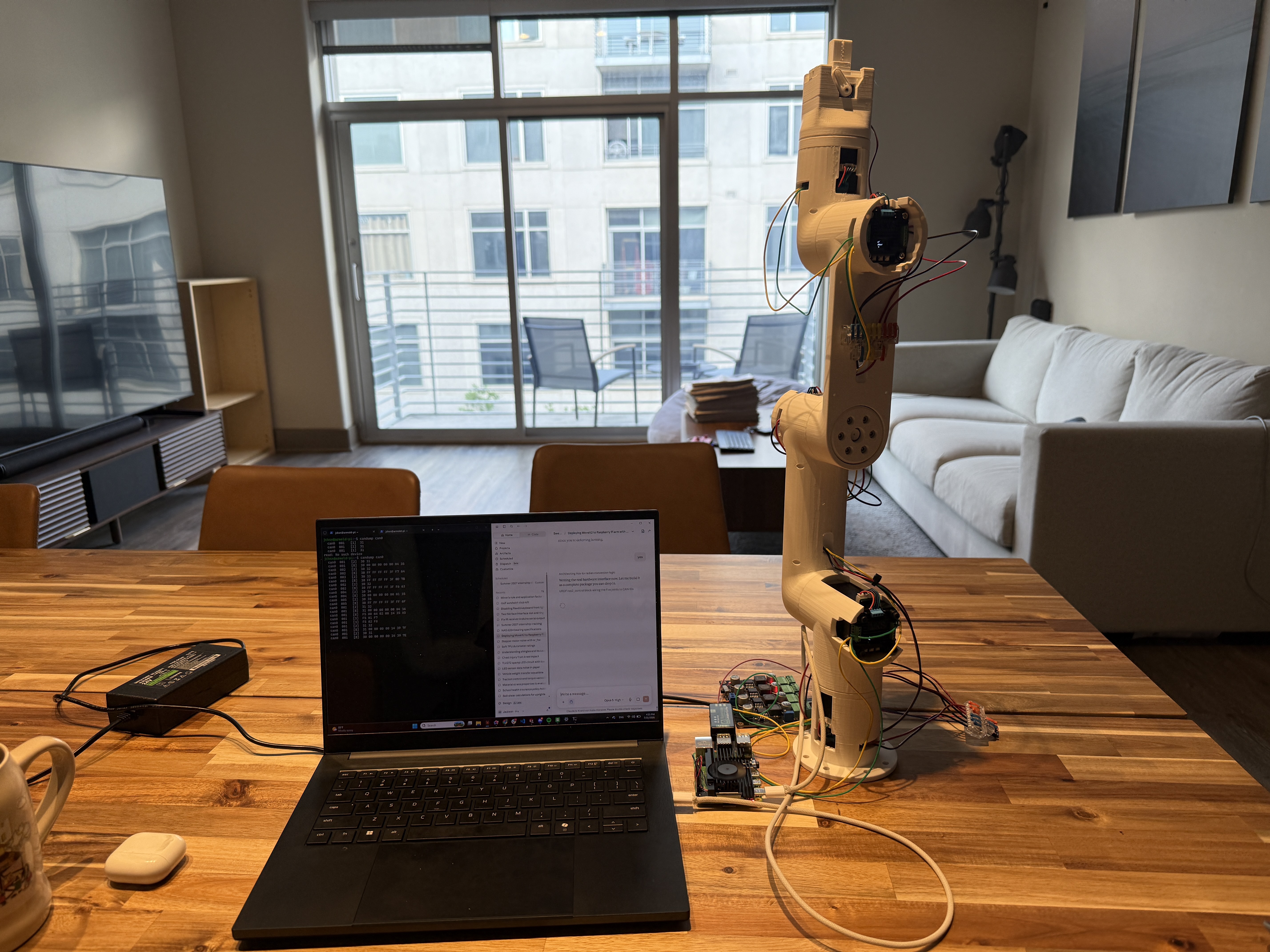
Armold is a 5-DOF robotic arm built with help from Sweep Dynamics, whose mechanical design it's based on. I built it around a completely different electronics and control stack — new motors, a CAN bus architecture, a custom ros2_control hardware interface, and modified printed parts to fit it all. The goal was a platform that runs a real motion-planning stack end to end: Cartesian goal poses down through inverse kinematics to closed-loop motors on a CAN bus.
Hardware
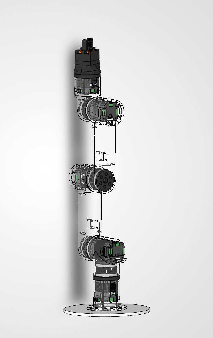
The joints are driven by MKS Servo42D closed-loop steppers in SR_vFOC mode, each on its own CAN ID (01–05). Output reduction comes from 1:26 cycloidal drives designed by Sweep Dynamics — high ratio in a compact envelope, low backlash, and enough torque density to hold the arm's weight without sagging between planning cycles. Backlash matters more than it seems: every degree of slop at a joint compounds through the kinematic chain into end-effector error, degrading how well the computed IK solution matches reality.
Integrating the reducers wasn't drop-in — I modified the provided models to match my motor mounts, shaft interface, and printer tolerances. Two lessons from that:
- SolidWorks STL export for URDF meshes: "Translate to positive space" must be off, and each joint needs its own coordinate system, or meshes land in the wrong place in the kinematic tree.
- Print tolerancing: Bambu Studio's XY compensation is applied per-side (radius, not diameter) — matters for cycloidal discs and pin housings that need to run without slop.
The gripper is a hobby PWM servo driven by an ESP32 over LEDC, on its own 5–6 V supply, kept separate from the CAN side.
Kinematics
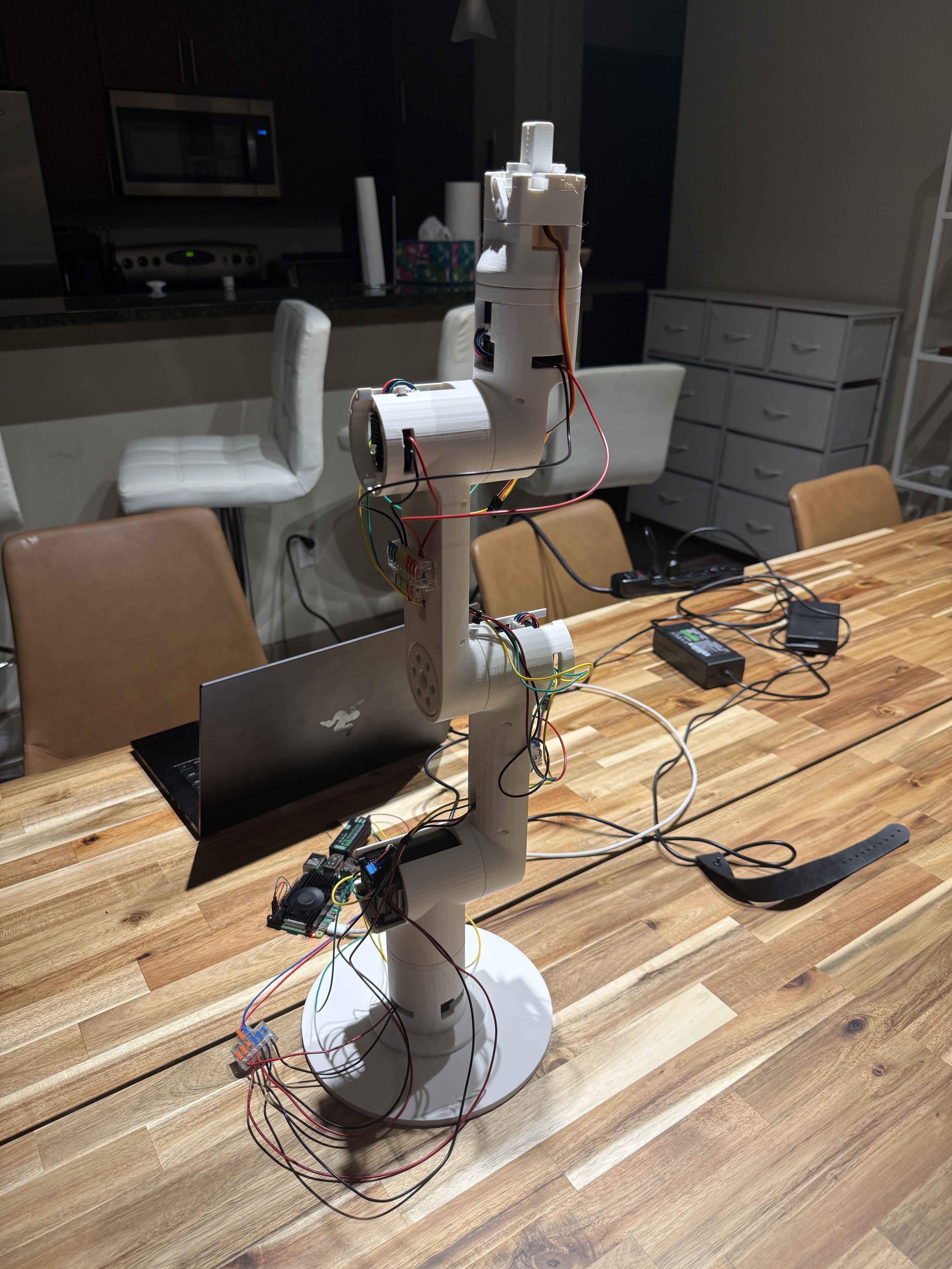
Armold is a 5-DOF serial chain — base yaw, shoulder pitch, elbow pitch, wrist pitch, and wrist roll — terminating in a fixed tool0 frame at the gripper mount, described in a URDF with each joint's axis and origin pulled from CAD.
Forward kinematics chains the joint transforms into a tool pose; inverse kinematics solves the useful direction — given a desired pose, what joint angles reach it — which is what makes the arm commandable in task space instead of joint space. MoveIt 2 solves this numerically from the URDF via KDL. A few implications worth knowing:
- 5 DOF can't reach arbitrary 6-DOF poses. One orientation degree of freedom is unreachable, so task planning has to leave a component free or accept solver failures on some requested poses.
- Numerical IK can fail even on reachable poses. KDL seeds from the current configuration and iterates; poor seeds or near-singular configurations (near full extension, wrist axis aligned with shoulder axis) cause timeouts.
- IK is only one layer. MoveIt runs OMPL for a collision-free path, then time-parameterizes it into a trajectory with velocity and acceleration limits before it's streamed to the controllers — the source of one of my more frustrating bugs, below.
Electronics and CAN
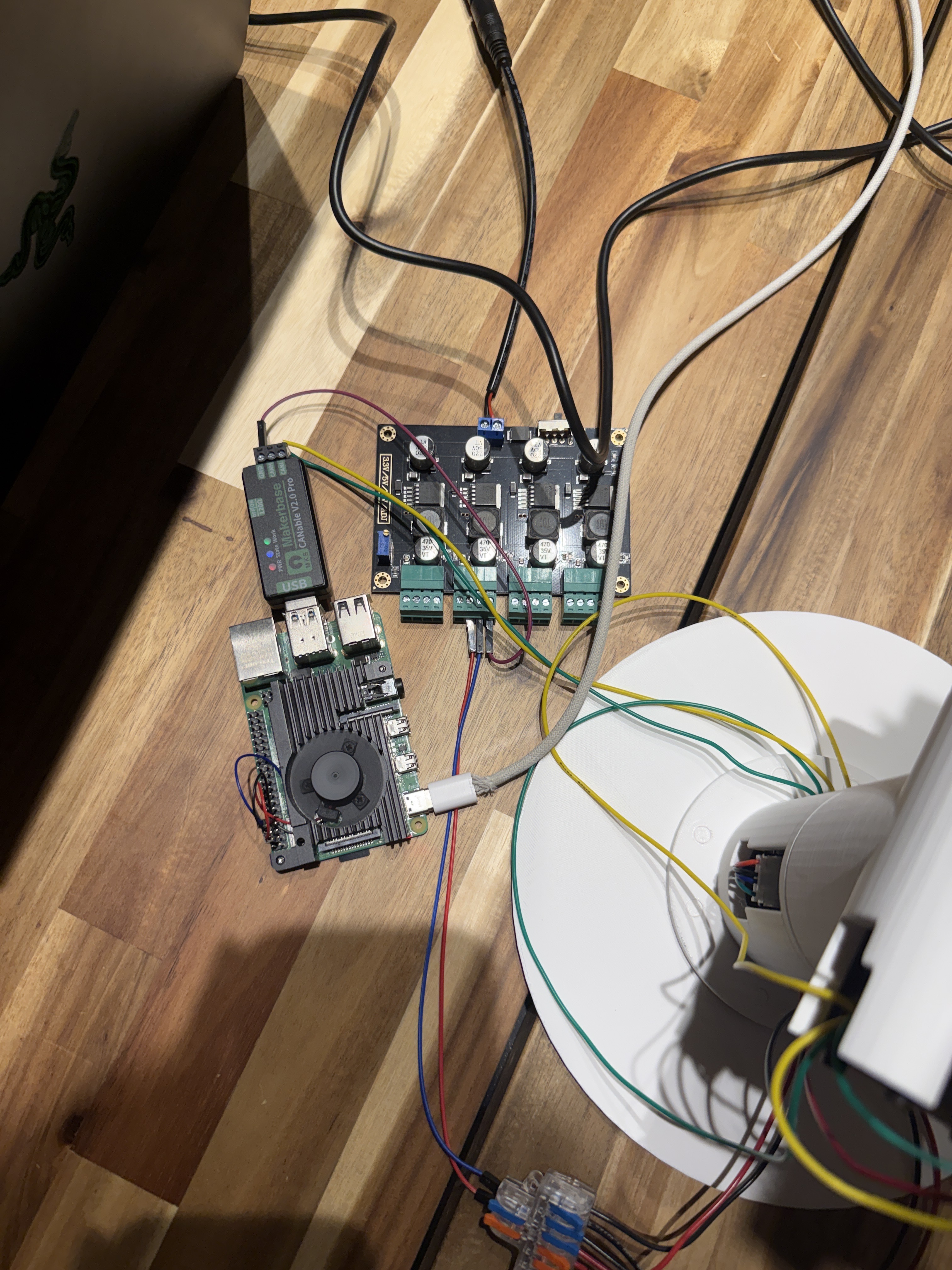
A Raspberry Pi 4 runs the stack, talking to the motor bus through an MKS CANable V2.0 Pro USB-CAN adapter, bridged into ROS 2 with ros2_socketcan on can0 at 500 kbit/s. The bus is a daisy chain of CANH/CANL with 120 Ω termination at both ends, motor power on a separate parallel rail.
Things that cost me time:
- The motors I already had were the RS-485 variant, not CAN — the Servo42D ships in both and they look nearly identical.
- Wire color isn't a reliable indicator of CANH vs. CANL; only the silkscreen labels are trustworthy. Swapping them kills communication without damaging anything, which makes it easy to chase the wrong cause.
- CAN needs a shared ground reference between adapter and drivers — single-point grounding, not tied into the high-current motor return path.
- Motor calibration failures were a wiring problem, not a sensor problem: a "Reverse Lookup Error" traces back to incorrect A+/A−/B+/B− phase wiring, not the mechanics.
- The constant high-pitched hiss in FOC mode is normal — the PWM current loop holding position. Rough buzzing or grinding is what actually signals a problem.
Software
ROS 2 Jazzy with MoveIt 2 and ros2_control, split across three packages:
my_arm_description— URDF and meshes, the source of truth for the kinematic chainmy_arm_moveit_config— SRDF, planning group, kinematics solver config, joint limitsmy_arm_hardware— a customSystemInterfaceplugin (ArmSystem) owning the CAN read/write path to the Servo42D boards
Development happens on a Windows 11 laptop through WSL2 (Ubuntu 24.04); the Pi runs headless over SSH as the deployment target, with CycloneDDS handling middleware across the two. I got the full pipeline running against mock hardware first — move_group, controller_manager, joint_state_broadcaster, arm_controller, and /joint_states all healthy — before swapping in real motors, so hardware bugs stayed isolated from planning/IK bugs.
Debugging Notes Worth Writing Down
The failures that ate the most hours were almost all configuration, not code:
joint_limits.yamlmust sethas_acceleration_limits: trueand amax_acceleration. Without them, IK resolves, OMPL finds a plan, andAddTimeOptimalParameterizationsilently fails on every one — RViz shows nothing useful, the real error only shows inrqt_console.- Always rebuild every edited package. Stale copies in
install/caused multi-hour ghost-hunts — building only the package you're actively editing isn't enough. - In Jazzy,
ros2_control_nodegetsrobot_descriptionfrom the/robot_descriptiontopic published byrobot_state_publisher, not as a node parameter. Passing it as a parameter starves the controller manager with no obvious complaint. - The controller config file must be named
ros2_controllers.yamland live in the MoveIt config package'sconfig/directory forMoveItConfigsBuilderto pick it up — anywhere else and it's silently ignored. - Exit code
-11on shutdown is usually just Ctrl+C teardown noise, not a startup segfault — checkros2 node listbefore assuming a crash.
Where It's Going
Next up is finishing the real CAN command implementation in the hardware interface's read()/write() bodies, then adding a camera. Longer term, the goal is using Armold as a platform for LeRobot/VLA experimentation, with the ros2_control hardware interface bridging learned policies to the motors.
One constraint already run into: the Servo42D closed-loop steppers aren't backdrivable, so kinesthetic teaching isn't practical with this hardware — any demonstration pipeline will have to come from teleoperation instead.